|
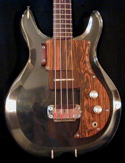
The Dan Armstrong bass guitar features a pickup that's just as ingenious and innovative as the various guitar pickups.
While it lacks the interchangeable pickup design of the guitar model, it can get achieve just as many (if not even more) sounds eminating from it.
This amazing feat is accomplished by the fact that the bass pickup is actually two totally different pickups in one housing.
Like the guitar pickups, the bass pickup was designed by both Dan and
Bill Lawrence who went on to say "We had
actually designed two different types of pickups for the bass instrument but Ampeg decided to only use the one."
The one Ampeg settled on was two pickups in one. Two single coil pickups stacked - one coil on top the other. Being the coils are stacked
the magnets are then placed along the sides of the coils. As usual for Dan Armstrong pickups - the entire unit is then encased in a brown
colored resin - thus making the bass pickup much like the guitar pickup - one of the earliest known potted pickups ever.
|
According to literature the bass pickup is known as the DB or 'Deep Bass' pickup which, according to Kent Armstrong
were wound with 43 gauge wire (AWG) on the top coil with 44 gauge (AWG) on the bottom coil. By turning the tone knob
down the signal runs through a capacitor, and as a result, only the larger (bass) coil underneath is activated. This
gives the instrument a thick, solid lower bass tone. By turning the knob up, the upper (treble) coil gradually gets
blended in to the already low end bass sound. As the tone knob gets turned up more, the treble coil gets more prominent,
while the lower bass coil begins to dissipate. With the tone knob full up, the larger bass coil underneath, along with
the capacitor, gets faded out altogether, resulting in a very trebly-midrange sound. So by simply adjusting the tone
control, the two coils can blend together, or apart, for a wide variety of sounds. The blending of these two pickups,
and sounds, is strictly a matter of personal taste and was Dan's way of getting the most out of a single pickup
bass guitar.
|
|
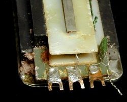
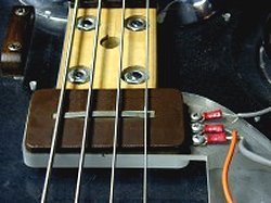
At upper left, and unlike the guitar model, the original bass pickup does not connect to the rest of the instruments circuitry by employing
banana plugs and jacks. Instead, three spade type lugs protrude from the pickup that anchor to the acrylic body using
three machine screws. The wiring to the rest of the instruments electronics are tightened underneath these screws as
well, as can be seen.
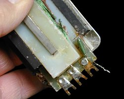
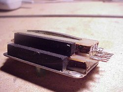
At upper right, around 1971 the bass pickup took on a somewhat different look. While made the same internally they now sported a new outward
appearance from those prior to it. Specifically, there was a rise in the center of the pickup that extended the length of the bar pole piece.
This additional resin was added to the top of the pickup to combat against flaking in prior versions. Because the pickup is actually two single coil
pickups stacked in one housing, there wasn't a whole lot of room for extra material so they just followed the arch of the pole piece.
|
|
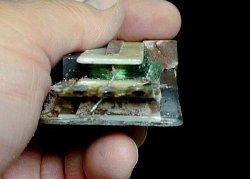
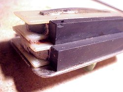
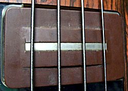
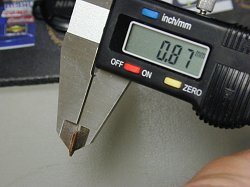
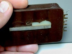
The brown resin encasing the pickup on my bass had been flaking off in and around the area of the bar magnet as can be seen below left so I
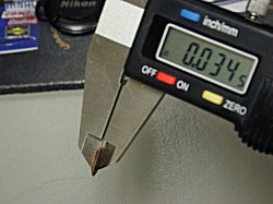
decided to take a piece and measure the thickness. As can be seen above left & right the resin thickness above the top coil bobbin comes in at just
over .034 inches or 0.87 millimeters. I'm sure that this measurement varies a bit from pickup to pickup, but its measurement should give us a brief
idea as to the approximate thickness of the resin in this area, and why once the resin gets brittle, it tends to flake away from this area rather easily
due to the lack of thickness and/or sufficient mass and helps explain the added material mentioned above.
|
|
At left, earlier pickups (like this one from my 1970 Dan Armstrong bass) have a lead wire protruding from it. Seen better in enlarged view,
it is briefly mentioned in the instructions for the bass guitar in Ampeg's Product Bulletin #17 which gives the procedures
for updating the Dan Armstrong guitars and basses. The procedure for the bass was fairly simple, step one consisted of nothing more
than soldering this lead wire to the nearest lug, or screw terminal on the pickup.
It was simple enough but I never got the chance to follow the instructions that would give my bass a wider range of tone as one day the
pickup went bad and had to be replaced. So I contacted Kent Armstrong who made a replacement pickup for me. It fit perfectly and sounds
great. He also made me a humbucker which I really like alot. Being my original pickup could not be rewound I just left things as they were
and moved on.
It would be none other than renown guitar luthier Dan Erlewine who
contacted me asking about this lead wire as he was restoring an original black Dan Armstrong bass for a customer. His experiences doing so
can be read in the April, May & June 2013 issue of
Vintage Guitar Magazine.
When the time came to install
the pickup and electronics he discovered, and thus had questions about the existance of a wire protruding from the pickup and was wondering how
it got tied in with the rest of the circuitry on the bass. Unfortunately I really had no answers for him but was determined to find out, so I told
him that my bass pickup also had the wire protruding from it and that it wasn't tied to anything. In fact, on my bass the wire was just lying there off to
the side doing nothing (or so I thought). I told Dan that I would inquire further into the matter, and try once and for all, to figure out the reason
behind the existance of the wire that was protruding from these pickups.
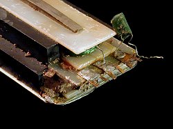
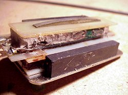
My first move, naturally, was a call to Kent Armstrong who informed me that the wire protruding from the pickup was not a wire, per se, but
actually the lead wires, or 'legs' of a capacitor that was actually inside, encased with the rest of the pickup coils within the brown resin. As seen
at upper right, when I removed most of the resin from my pickup I discovered the internal capacitor that Kent had spoken of.
Above left & right, the internal capacitor seen from a top-down view. When I removed the brown outer resin casing from the pickup the
capacitor was neatly tucked into the side of the top coil's bobbin. One of the capacitors legs was run through, and soldered to, the screw lug
or terminal, which happens to lie directly beneath the capacitor itself. Then the two legs of the capacitor are tied/twisted around one another
and soldered together, creating the look of a single, bare wire that protrudes from the pickup (once the brown resin that makes up the outer casing
of the pickup hardens up).
As seen above left & right, the ground (or common) of the pickup can be seen soldered to the middle lug. Seen better in enlarged
view, you can see can see where the wire runs from the top coil, through the middle lug, down past the bottom coil and solders to
the metal base plate of the pickup.
To understand what Dan had designed with this pickup I decided to contact two specialized people. Once again, I called upon Mr. Kent Armstrong and
my old friend Mr. Elon Coats. As a renown pickup maker, Kent has been contracted by Ampeg to reproduce his fathers pickups for the reissue acrylic
models and has all the spec's to the original pickups that Dan and Bill Lawrence produced for the original models.
Elon holds an EE degree and prior to his retirement was a chief desin engineer at Peavey Electronics where he had designed countless musical products.
After talking with them & showing them photos of my bass pickup, as well as the literature from Ampeg's Product Bulletin #17 - I asked for their thoughts
as to what this was all about. Not surprisingly, they independently came to identical conclusions, stating the following:
'The Dan Armstrong bass tone control operates a bit different than the standard treble roll-off that most guitars and basses use. With independent top
and bottom pickup coils, the lower one is used to boost the bass frequencies while the top coil has the bass stripped away and added to the mix. The
bottom coil is shunted to ground when the tone control is turned fully clockwise, leaving the top coil alone to output the signal.
The top coil has the bass stripped away by using this internal capacitor which is wired in series with the coil. The capacitor leads that protrude from
the pickup do so for a reason. Being the capacitor was in series with the top pickup winding, the only way to verify that the top winding was not bad,
or (open) was to bring out the actual winding - via the capacitor leads... for testing. An ohm meter doesn't work through a capacitor, only something
with a DC resistance like the wire of the winding. So the capacitor leads were extended outside the pickup strictly for testing purposes.
Since the cap is in series with the pickup and used for the treble side of the tone control it gave a rather thin sound when the tone control was
turned up all the way and was probably not what you would want by itself. One can only speculate that not everyone cared for this sound, or that at
least Dan didn't. For whatever reason, he decided it was time for some tonal modifications to be made to his instruments. No sooner had he submitted
his wiring modifications to Ampeg, had they began producing the newest acrylic basses (and guitars) complete with their respective, and new..... wiring designs.
While instruments were leaving the production floor at Ampeg with the new wiring changes it would take a little longer for them to get their
literature out to their dealers and customers. But on March 8, 1971 Ampeg released Product Bulletin #17 - Procedures For Updating Armstrong Guitars
And Basses stating "In an effort to improve the tonal response from the Armstrong Instruments, several changes were made in their respective control
assemblies." (This literature can be accessed in the Brochures section).
For the bass guitar the update totally changed the tone control circuit to give a better tonal adjustment that had more low and mid frequencies that
were lacking with the series cap. With the series cap in place, there was nothing you could do to get that tone since the cap stripped it away. In
order to get more of these 'low and mid frequencies' it became necessary to bypass the internal cap. To bypass the internal cap Ampeg's Product
Bulletin instructs one to solder the lead wire of the cap (which is the bare wire extending from the pickup) to the nearest pickup lug - which is,
ironically, the very same lug that the 'other' side of the capacitor is soldered to.
By soldering that extended lead wire of the internal cap to the very same lug as the wire from the otherside of the internal cap - the capacitor is,
then, shorted across itself, and becomes nothing more than just a wire in series with the coil. As such, the cap that was internal to the pickup is
now bypassed, no longer active and the pickup winding is now directly connected and provides a full range output without attenuated low frequencies.
In Ampegs Product Bulletin they did have you replace the internal cap with a new, and different capacitor of a different value, which will allow more
low and mid frequencies to pass in addition to the treble frequencies. However, this new capacitor now resides in the control cavity of the instrument.
So, by bypassing the internal cap, the full range of the pickup can be utilized for tone adjustment since the frequencies could be easily tailored outside
of the pickup. As such, the pickup is now much more versatile as one is no longer stuck with the pickups default frequency response like before.
To make things even more versatile, a switch was added along with a second capacitor of a different value than the first. So by flipping the switch,
you select a different value of capacitor, both of which work along with the tone control for a myrid of different sounds. Earlier basses that did not
yet employ a switch could order the parts from Ampeg or acquire the parts from a local electronics store. Lastly, and for earlier basses that did not yet
employ a selector switch - a hole would have to be drilled through the scratchplate for it.'
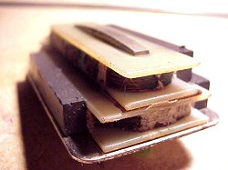
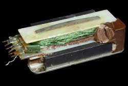
Seen here is a later Dan Armstrong bass pickup with the resin stripped away. One can easily see the two coils, one on
top the other. Notice how the top bobbin is actually secured onto the lower bobbin using a form of glue or epoxy to
eliminate any resonant vibration. Photos are courtesy of Bill Richardson.
At upper right, and seen better in enlarged view, coil wires from the top coil can be seen directly attached to the lugs without
any capacitor (meaning this was a later made pickup - after the aforementioned changes to the bass pickups). The middle one is ground,
or common and will travel down to the lower coil where it too, will have a wire attach to this ground wire,
which will continue down and eventually be soldered to the base plate of the pickup.
Instantly obvious is the unusual placement of the pickup magnets resting beside each coil. Two huge ceramic magnets
were placed alongside the lower coil, one on each side, while the top coil only features one ceramic magnet placed
on the north side of the pickup.
At left, notice the extra piece, or shelf - added to the top coil bobbin for the spade lugs to reside on. Also in larger view, notice the coil wires
as they are soldered directly to the lugs, without a capacitor - again an indicator of a later pickup.
On the right, notice the dark colored glue or epoxy underneath the pickup bobbins - used to help secure them in place while also isolating them from one
another as well as from the metal base plate on the lower coil.
Like my bass pickup, this pickup had gone bad as well and had the resin carefully removed from it by guitar luthier Bill Richardson, who sent me these
photos and wisely pointed out that he "hopes that it will help players understand how these neat sounding pickups work......... and sometimes die."
menu
Names and images are TMand © Dan Armstrong / Ampeg. All rights reserved.
All other names and images are TMand © of their respective owners. All rights reserved.
|
| |