When Dan Armstrong parted company with Ampeg in mid to late 1971 due to amplifier disputes he also decided that it was
time to close Dan Armstrong's Guitar Service. Along with his two elderly sons Kent & Eric - Dan picked up & moved to
England and went to work briefly for Orange amplifiers. Kent Armstrong goes on to say "he only worked for them briefly - a few months at the most."
It is unknown what transpired in that short amount of time. Perhaps Dan didn't hit it off with the people at Orange,
or perhaps he was only called in as a consultant. Whatever the case, it wasn't long after his time with Orange that he
started a new amplifier line with Boosey & Hawkes
who are probably best known for their Laney amplifiers.
The Dan Armstrong amplifiers were unlike anything ever seen before. Gone was the usual circular volume & tone type
potentiometers and knobs - and in their place - graphic equalization sliders that were referred to as the 'tone
shaping system', allowing one to tailor their sound far beyond the means of the typical volume, bass, treble and
midrange controls present on other amplifiers of the time.
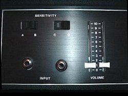
As seen upper left, the input stages of all the Dan Armstrong amplifiers but the slave amps employ two input jacks
along with sensitivity switches above them. The left jack is wired for lower signal inputs while the right jack is
wired for higher output devices. On both the lower & higher input stages the rocker switches above the jacks serve
to help a given instrument's output better match the amplifiers input stage. Rocking the switch one way or another
increases or decreases the signal of the given input. This allows the Dan Armstrong amplifiers to be very versatile,
and capable of virtually any instrument to be plugged into it. Next to the input stage is the volume slider controls.
The left slider controls the amplifier volume of the signal on the left 'lower' input jack while the right controls
the amp volume of the right or 'high' input jack.
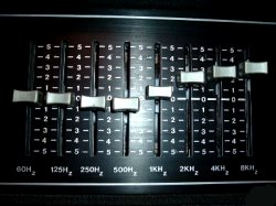
At right, and again, as seen on all Dan Armstrong amplifiers but the slave amps is the 'Tone Shaping System'
consisting of eight slider controls with each slider controlling approximately one octave of the audible musical
range 60Hz - 125Hz - 250Hz - 500Hz - 1KHz - 2KHz - 4KHz - 8KHz. Moving the slider up or down can cut, or boost as
much as 15dB and any frequencies within that range can be accentuated or virtually eliminated - making the tonal
variations of these amplifiers nearly limitless.
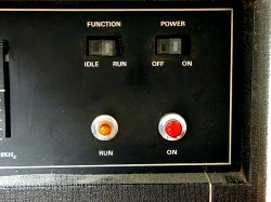
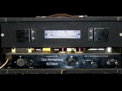
As seen upper left - off to the right hand portion of the Dan Armstrong amps lie the standby and power controls in the
form of two rocker type switches that lie above a red and an amber light. Like most other amplifiers on the market -
when the power switch is turned to the on position the red light comes on. When the function, or standby switch is in
the 'run' position it is lit - and the amp is running, and no longer on standby.
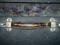
At upper right, the Dan Armstrong amplifiers all come with leather styled carrying handles on the top, and in the case
of the larger combo amps - these handles can be found on the sides as well.
The backside of all the Dan Armstrong amplifiers are the same as well. As seen upper left, and in the upper left of
the amp chassis is the white power cable entering into the amp while immediately below it is a 2 amp mains fuse.
Immediately to the right of both of these is a voltage selector switch which allows one to plug the amp into either a
115, 220 or 240 volt power supply which makes it an amplifier that can be used in the US or Europe without changing
anything more than the selector switch and the plug that fits the outlet of choice.
To the right of the voltage selector switch is a 1 amp high voltage fuse protecting the electronics inside. In the
middle of the chassis is the power rating of the amplifier directly under the Dan Armstrong name, while off to the
right is a selectable speaker impedance switch allowing for a 4 - 8 or 16 ohm speaker load to accommodate many
different speaker cabinets. Two output speaker jacks lie to the right of the speaker impedance switch, while two
line outputs - called 'slave' outputs lie at the far right of the rear chassis. In brief, the amp is built to work
under a myriad of possible scenarios.
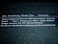
Seen in the upper portion of the rear of the amp are two metal plates protruding outward and in different directions
while allows the musician a quick & convenient way to wrap up the power cord as well as other cords if needed. In the
center between these two plates lies a thin metal plate giving the amps serial number, model number and total wattage
output. At upper right, a close up view of the plate. Notice how the amp is 'made' by the Electronics Manufacturing Co.
Ltd. of England and 'distributed' by Boosey & Hawkes (sales) Ltd.
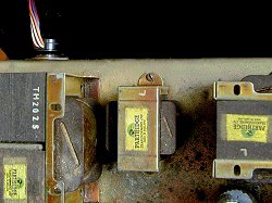
As seen upper left, and like everything else Dan built, these amps came with some of the finest components on the
market for the time. When it came to making amps - all of the Dan Armstrong amplifiers were fitted with
Partridge brand transformers throughout. Partridge transformers are manufactured
by Mercury Magnetics
, in Chatsworth, CA, who acquired the Partridge business.
Steve Honest, who both makes & sells amps at London's 'Rock of London' goes on to add "The thing with transformers
is mass. The bigger, heavier transformers seem to have more body and tone in the low end, with lots of 'grunt' and they
deliver it fast. This makes an amplifier very responsive - which in turn makes the overall tonal quality of an
amp much better. Partridge transformers were very good, and a favorite of mine, with loads of low end and delivery."
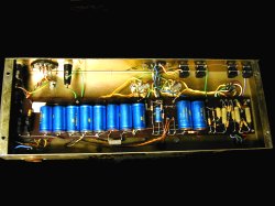
At upper right, the internal components of my Dan Armstrong 60 watt head can be seen.
Back at the upper left, notice how the cables that run from the pre-amp section of the amp connect to a male plug that
in turn, plugs into a female plug mounted on the amps chassis. These plugs are actually vacuum tube type plugs, with
the male plug like the pin arrangement one normally see's on the bottom of a large vacuum tube like a 6L6GC or EL34.
The female receptacle is mounted to the chassis in the usual way that it would be to accept a vacuum tube. However,
in these amps the plugs were used, not for tubes, but for wiring connections between the pre-amp and the power amp.
Over at the right, and seen better in the enlarged view, the wiring from the female receptacle jack to the power amp
stage can be seen.
continue
menu
Names and images are TMand © Dan Armstrong / Ampeg. All rights reserved.
All other names and images are TMand © of their respective owners. All rights reserved.
|
| |