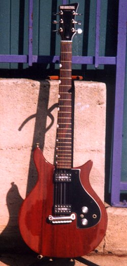
With the template complete, the body style took on a new look. The cutaway horns were trimmed down and flared out more
with the lower cutaway greatly trimmed, or shortened in order to allow the player easy access to the upper frets. The
scratchplate was redesigned as well which reduced it's width as well as its upward travel into the lower horn. Instead
of following upward along the shape of the lower horn it ran straight out, then back toward the bridge.
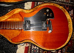
As can be seen below in both photographs, both these instruments, as well as their predecessors have their strap pins
located in virtually the same areas on the guitar body as the Dan Armstrong Ampeg acrylic instruments.
courtesy of Craig Buzzart
|
|
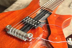
As seen above both left & right Dan began to experiment with the later versions of these instruments by adding a
second pickup on some models. Notice that the model on the right employs a selector switch allowing for numerous
wiring schemes & sounds. However, according to Kent Armstrong "the
guitars featured no such switch at all. Any switch on these guitars was added later and is a modification."
Kent did go on to mention that the instruments were wired in such a way that when the tone control got turned all the
way up it would then short circuit one-half of the humbucking pickup, thus making it a single coil - which would
serve to brighten the sound beyond the '10' setting on the tone control. Photos are courtesy of Logan Beveridge.
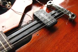
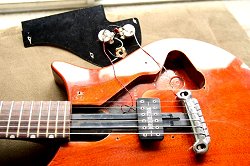
With the scratchplate removed the routed cavity of the guitar, as well as the aluminum ramp that the pickup slides on
can be more easily seen. At left, notice how the ramp actually travels into - and comes to rest in the base of the
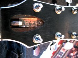
neck. Also notice the stamped in numbers seen just to the right of the pickup. According to Kent Armstrong this was
the same number that was written in underneath the truss rod cover on the headstock. It served as both a quality
assurance stamp as well as a series of numbers depicting the year as well as the portion of the year it was made in as
already mentioned. The numbers can be better seen in the enlarged view depict 4324. Kent still has
the stamping tool he used to stamp these numbers. Seen at upper left - notice how one can easily depict where the
scratchplate resides on the body due to the lighter color of the wood &/or finish which has been shielded from stage
and other light sources.
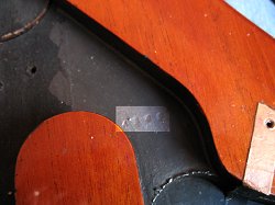
As seen upper left - and with a portion of the photo highlighted to reveal the serial number of 4362 making this
instrument a 1974 model, made in the 3rd quarter, and the 62nd one made in that quarter. At upper right, the body also
gets stamped with the same number as the neck. Although highlighted in this photo as well it is still somewhat
difficult to see due to the shielding type paint that was applied later by it's owner. Seen better in the enlarged
view the body shares the same number of 4362.
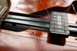
As seen upper left - a closer view of the sliding pickup and the ramp. Notice how thin the pickup is and also how there
are no mounting screws seen on the pickups on this guitar (more easily seen in larger view). Although unknown as to why,
apparently the pickups were attached to the ramp from below on this model, thus eliminating the need for any mounting
screws on top.
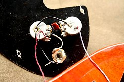
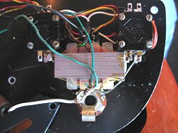
According to Kent Armstrong (and as can be expected) the London instruments employed volume & tone potientiometers
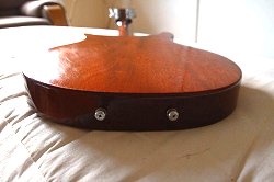
that were made in England. Between them lies a .022µ capacitor all of which can be seen at left. At right, and
like the Dan Armstrong instruments before them, two strap pins are fixed on the bottom of these instruments for the
very same reasons the acrylic instruments employed them. Notice the somewhat marble look to the wood on the backside
of the body.
At upper left, A two-pickup London model rests in its case. Notice the Telecaster style knobs and added selector switch. At upper right,
and with the scratchplate turned over, Allen Bradley push-pull type pots have been added are wired in along with the switch for various
wiring schemes and tonal control. Photos are courtesy of Paul Q. Kolderie.
Also seen is a replacement transformer which converts the instruments low impedance signal to high impedance so that
the instrument will work properly with an amplifier, though according to Kent Armstrong "some amps have both a
low and high input stage, (or input jacks) on them, and if the transformer on the instrument were eliminated altogether
one would have to use the low input." As seen upper right, and as Kent went on to explain "If one were going
to install a replacement transformer, an 11 or 12 to 1 type ratio transformer would be needed".
continue
menu
Names and images are TMand © Dan Armstrong / Ampeg. All rights reserved.
All other names and images are TMand © of their respective owners. All rights reserved.
|
| |