|
|
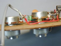
Both the guitar and bass have the volume & tone pots, selector switch and output jacks all mounted on, and wired in
underneath the scratchplate. When asked Dan said he made it so that his instruments would be easy to service.
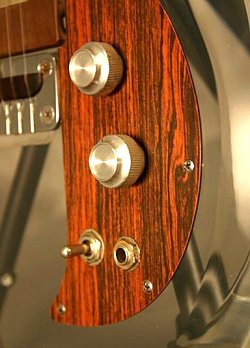
The aluminum knobs nicely set off the difficult combination of the clear acrylic, the wood patterned Formica, and
chrome plated hardware around them.. Earlier brochures reveal a different set of knobs than these and Dan points out, "Ampeg had
planned to build a line of mixers for PA systems and as a result, had acquired thousands of these knobs - the same kind that
matched their amplifier line. But the mixers had problems and the systems never made it into production and were discontinued.
Being left with so many knobs, Ampeg approached me and asked if I could make use of them - I
said sure!"
By loosening the strings and removing the scratchplate screws, one can gently slide the scratchplate out and away from the
acrylic body just enough to flip it over, to clean &/or work on the controls underneath.
|
|
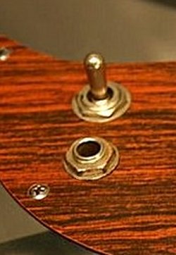
As convenient as the faux-wood Formica styled scratch plate is, its thin and brittle composition renders it fairly weak. In today's
electronic world - wireless technology for guitar and bass is ubiquitous, but in the late 1960s until the mid 70s or
later, patch cords were required to hook one's instrument to an amp.
Unfortunately, and as seen here - for those who did not loop their patch cord through the guitar strap prior to plugging it into the instrument
- and then accidently stepped on their patch cord would usually have anything from a cracked to a massively broken scratchplate which usually
resulted in anything from a repair to a replacement.
|
|

|
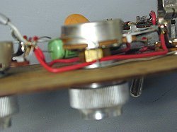
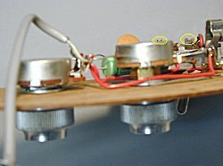
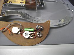
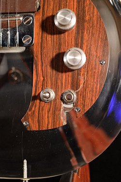
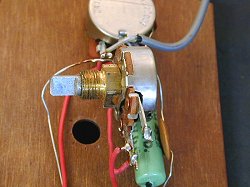
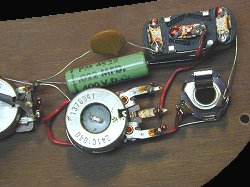
At left, underneath the scratchplate lies CTS brand volume and tone potentiometers. Notice how the tone control pot sets up higher than the
volume pot. At right, it appears that a brass spacer - of sorts - raises (or lowers - depending on) the tone potentiometer relative to the
volume pot. At right, and seen in the closer view it appears to be a brass nut acting like a spacer.
|
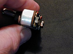
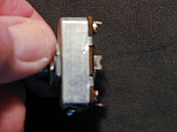
As seen at left, with the tone pot removed from the scratchplate - it reveals that what looks like a brass nut acting like a spacer is not a
brass nut at all. While it's a spacer - it's a spacer that's been machined right into the actual pot. Obviously this was to space the pot away
from other pots and components in order to allow more pots to be postitioned closer together in tight-fitting enclosures.
|
But there was no need for such a pot, for there was plenty of room for both the volume and tone pots on the scratchplate which begs the
question ..... why? With plenty of space for both pots, coupled with the additional cost that more brass would run and it makes no financial
sense to use pots like these.
It was then that it dawned on me. When I asked Dan about the use of Ampeg knobs on his instruments (seen at the top of this page) his answer
very likely applied to the potentiometers that those knobs set upon. I'm betting that these pots were the same, or near same value that Dan
was going to use for a tone control on his instruments. Althought spaced further down in the control cavity they still fit and would work.
I'm guessing that the additional spacing in height of these pots suggest that in those PA systems that Ampeg intended to produce PA control
consoles that they wanted to keep down in physical size. They would accomplish this by placing control knobs closer together, thus they were
going to stagger mount the controls. It's only a theory but it makes sense
|
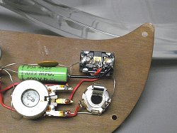
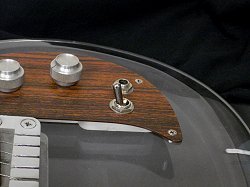
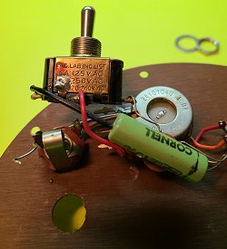
In addition to a volume and tone potentiometers the scratchplate housed a 3-way selector switch that was supplied by Carling Technologies.
Lastly, a Switchcraft output jack tops off the list.
As fate would have it, Dan originally had no plans for a selector switch in his guitars. Bill Richardson goes on to
say "Dan said that after the prototype was made and shown to Ampeg they simply said 'nobody will buy a guitar without a switch' - to which
Dan replied...Guys, it's only a single pickup guitar with a single-coil pickup." Basically he was trying to keep costs down.
But Ampeg was adamant, and Bill continues... stating "needless to say he was told to put a toggle switch in the
guitar ...and eventually the bass too. The bass one makes sense to me but the guitar one is a bit needless. If ya
think about how cool, funtional and downright modern the rest of his pickups, pot values and tone cap choice was
design wise in 1969, a switch to turn the tone to zero kinda reaked of afterthought to me. Basically, Ampeg got their
way and wrote about it in their marketing blurb."
|
|
|
At left, the switch on my 1971 Dan Armstrong model had gone bad. It was actually pretty 'floppy' when I bought it, so it didn't shock me when
finally it gave up the ghost. I knew it was a long shot at best, but I nevertheless contacted Carling Technologies - the company that actually
made the switch for the Dan Armstrong · Ampeg guitars back then.
I was curious to see if they had some type of replacement switch. Granted, I pretty much figured that they still made single pole - double
throw (SPDT) switches - but most importantly, I wanted to know if they still made such a switch that would be able to
fit within the shallow confines of the control cavity on the Dan Armstrong instruments.
I'm guessing that you know the reply that I got. I got a link to their site (that I had already looked over) - showing their line of SPDT
switches, but no mention at all regarding the depth of the switches - so I shot off another email stating I had looked over their site in regard
to their line of switches but am looking for one that is no more than 3/4" in depth once installed. Surprisingly a nice gal responded saying
their "most shallow switch measures 1.5" in depth below what it's installed onto." - So that was a bust.
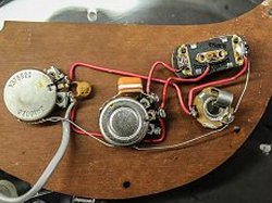
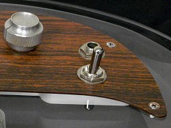
At right, a closer look at the switch shows that it is indeed a Carling Technologies make, but the red or blue paint that's normally seen over
the soldering joints were lacking and I was convinced that the switch had been removed or replaced - at one time.
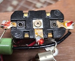
At left, when I lifted the control plate over to get to the switch I noticed some unusual U shaped tabs sticking up from it. At right, and
circled in yellow, the tabs are easily seen. I also noticed that wires were soldered to a portion of these tabs.
At left and right, with the switch removed it was then that I had an epiphany, and it all made sense. I finally figured out that these 'U' shaped
looking tabs were the remains of the three screw-type terminal lugs that most switches have for one to tie their wires onto. With the screw lugs
being ground down like this, it became quite obvious that the Carling switch would not fit within the confines of the control cavity of the DA
guitar. As a result of this, the lugs were ground down at until the switch would fit. The wires, then, were soldered to what remains of the
three lugs on the switch.
With the lugs ground down like this, and the fact that the usual red or blue paint that Ampeg applied on all their soldered connections was
missing, I was convinced that the switch had to be a replacement - a switch that a past owner most likely received from Carling Technologies. I
thought that perhaps when the switch arrived that the owner had no choice but to alter it to fit within the shallow confines of the control
cavity of the instrument. The owner, then, ground down the screw-type terminal lugs and soldered the wires directly to the remains of those lugs
at the bottom of the switch. This is why there was no paint on the solder connections.
|
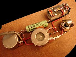
You can imagine my surprise, then, when I found this photo of the wiring underside yet another Dan Armstrong guitar scratchplate - this one
was online and revealing the exact same switch as my guitar had - complete with the ground-down screw terminal lugs. But unlike my switch, this
one shows its soldered connections complete with the factory paint in-tact over the solder joints. Knowing it left the factory that way totally
shot down my 'switch replacement' theory. Needless to say, I was in a state of shock when I learned all this. It all seemed so convoluted for
a factory production instrument.
|
|
The practice of cutting down screw terminals on the Carling Technologies switch would continue until sometime in late 1970 or early
1971 when a different switch was employed that's often referred to as the 'Second Generation Switch'.
At first, I just thought this switch did not have screw type terminals, but the longer I looked at it the more I realized it did. The
difference is the terminal screw legs are of a much thinner metal and were simply bent outward. With the screws removed, the screw holes were
something to run the lead wires of the capacitors and wire through prior to being soldered - which is what can be seen here.
|
|
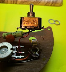
As seen at left, one side of the switch reads:
Carling
Made In U.S.A.
|
|
As seen at left, the other side reads
UND.LAB.INC.LIST
5A 125V. AC
NA 250V. AC
120 - 240VAC
|
The Carling name, of course, is short for.... you guessed it... Carling Technologies - the same company that made the first switch. One
can only assume that, for whatever reasons - probably financial - they changed the switch. But that was then, and this is now. Carling
Technologies was of no help when I contacted them. My search for a replacement was still underway.
While I didn't 'spend the last year' there, I was out 'Rocky Mountain Way' visiting relatives. After combing the internet back home and
searching virtually every guitar store and shop in the Colorado Springs area, my wife encouraged me to try a hardware store. Knowing this was a
complete waste of time I nevertheless accompanied her to the Ace Hardware store in Florissant, Colorado. After looking around I decided to humor
her and walked down aisle #3 where they had switches. I have to say, I was very surprised to witness such an impressive display, for they had
what looked like every switch made. As I slid open the drawer labelled 'SPDT On-Off-On' there was but one switch left. As I pulled it out and
gazed at it through the clear side of the plastic bag I couldn't believe what my eyes were beholding.
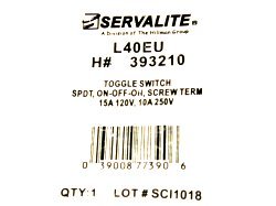
At left, the switch I was holding was a Servalite L40 EU - H# 393210 and a division of the Hillman group. I couldn't believe my
luck at finding this in a hardware store of all places. Frankly, I've never before seen such a shallow switch as this. As I worked the bat
handle back and forth to make certain it felt correct I'm told that the next two words out of my mouth was 'Holy Crap'!!
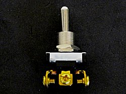
At right, I knew that the screw type terminals would have to be addressed, but once addressed, I could tell that the switch would easily fit in
the control cavity of my Dan Armstrong guitar. Once home I did a side by side comparison of this new switch to the original Carling Technologies
switch. The bat-handle looks and feels like the Carling switch. Its Zinc plating nicely matches not only the original switch, but the chrome
plating of the surrounding hardware quite nicely. While it may not be a 100% exact copy it is, in my opinion a 99.8% copy. Honestly, short of
using a magnifying glass and measuring equipment - you'd never know it was a replacement once it's in place. Only by 'checking under the hood 'so
to speak' - would one know.
Unfortunately, this switch, (like almost everything these days), is made in China.
So as per my disclaimer I cannot - in good conscious - recommend the purchase of this
switch at this particular point in time given the world pandemic we are all facing. If you should decide otherwise, I would recommend taking the
necessary precautions of wearing an N95 mask and vinyl gloves. Then apply a 90% or stronger rubbing alcohol solution to the switch thoroughly
before working with it.
Lastly, I am not certain, as there was no label or printed matter of any kind, but I will point out that like most everything else produced in
the world, I feel it's safe to assume that this product is likely listed in the
California Proposition 65 Warning which also may be a concern to some.
Once I had the switch my first step was to take a page out of Ampeg's 'play book' - which was to remove the screw type terminals underneath the
switch. To do that, I originally broke out my Dremel tool with a cutting type bit to cut through them, or at least grind them down. Wearing
goggles and gloves I started working on the middle tab. But looking at the dents on that very tab in the enlarged view you can see that I wasn't
making any progress, for the cutting bit was dancing all over the place despite my best efforts to hold it in place. As I turned off the Dremel
tool in defeat, I thought to myself that there 'has' to be a better way to do this.
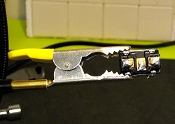
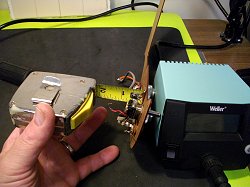
As seen at left, it was at that moment I looked down into one of my guitar repair tool drawers and noticed my pair of StewMac Fret Nippers -
used for trimming frets. Ironically, over the years I've used them for almost everything but frets. This time I slid the jaws over the
screw terminal tabs and applied mild pressure. In a matter of seconds the tabs were all gone - with a nice clean, even cut leaving only a very
tiny curl left - just enough to tuck a wire into solder it in place. I discovered later, however, that even the tiny curls would have to be
nipped off as well.
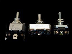
At right, three switches. From left to right - A Gardner Bender SPDT switch. These are the type you will always find and would work but in no
way will they fit the shallow depth of the control cavity. The next switch is the original Carling Technologies SPDT switch with its ground down
terminals. The bat handle appears to be much shorter on this switch but in reality it isn't. This switch is broken so badly that its bat handle
literally dropped 'down' into the inside of the switch. Last in this photo is my new Servalite switch - also seen with its screw terminal tabs
removed. Notice that the body of this switch is the same depth (if not a tad less) than the original. I did notice however, that it has a few
extra mounting threads up top compared to the original. But being such a shallow switch I knew this could be worked out.
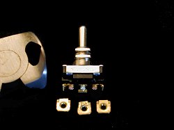
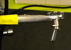
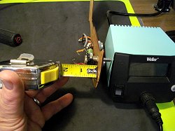
At left, prior to soldering the switch in place, and because of the aforementioned 'extra mounting threads' I again grabbed the fret nippers and
removed as much of the screw terminal legs as possible as I knew I would want this switch 'down on the deck' - literally lying on the bottom of
the control cavity. After that, I scuffed up the metal surfaces where connections would take place - so that solder will adhere to those
surfaces. I then tinned the areas with solder. At right, I did the same procedure for the ground wire, though after taking this photo I had to
laugh at myself as only then did I realized I tinned the wrong side, which required me to remove the solder from this side - scuff up the other
side and tin it to accept the ground wire. The ground wire is now soldered about where the alligator clip is seen in this photo.
At left, and as stated earlier, this switch does have a few more threads at the top of it than the original Carling Technologies switch, plus
its bat handle measures 2/16ths of an inch taller than the original - so for those hard-cores among us - it's not totally identical,
but after 50 years I believe that "totally identical" is an unrealistic goal. The good news is that the shallow body depth of the new switch
lets one lower it enough to offset these "extra threads". The depth of the control cavity is 3/4" except for a small area behind the output jack
where it's machined in at one inch to accommodate the length of the guitar jack. As seen at left and right, I set the bottom of the switch right
at 3/4" and tightened it down securely.
At left and right, with the switch securely tightened down, it's time to solder the wires to the new switch. Seen better in the enlarged views,
just solder the wires to the same places that they were originally soldered to. If you've detached the wires and forgotten where they went
you can follow the guides below:
At left, is the wiring scheme of the 1969 Dan Armstrong guitar which is different than later models.
1) The wire from the Mullard 'Tropical Fish' capacitor goes to the left, or closest terminal of the switch.
2) The wire from the center leg of the tone pot goes to the center terminal of the switch.
3) The wire from the positive terminal of the output jack goes to the far right terminal of the switch.
4) The wire from ground side of the output jack goes to the ground, or metal casing of the switch.
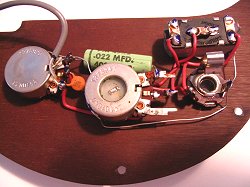
At right, is the wiring scheme of the 1970-71 Dan Armstrong guitar which is different than the 69 wiring
1) The leg from the tan colored disc capacitor goes to the left, or closest terminal of the switch.
2) The leg from the larger lime colored Dubilier capacitor goes to the terminal at the far right of the switch.
3) The wire from the center leg of the tone control gets soldered to the center terminal of the switch.
4) The wire from ground side of the output jack goes to the ground, or metal casing of the switch.
Even after soldering, I nevertheless used an ohm meter, and put one lead on the center terminal of the switch, and the other lead on the rear
terminal, then to the front - just to make sure the switch and connections were good.
At left and right, the final product, looking and sounding great. Up on top I decided to use the flat washer from the original Carling
Technologies switch - just to help give it a little bit of that 'aged' look. While the original Carling switch would now be more useful as a
paper or a fishing weight, I kept it in the pickup compartment of the guitar case as I know collectors can be a very quirky bunch and would no
doubt actually want it someday for whatever reason. However, for the rest of us - who just want a good working instrument, it should come as a
bit of comfort to know that there's one viable option for your Dan Armstrong · Ampeg guitar. Given how companies change
products all the time, and, given I have another Armstrong guitar (though it's switch feels fine and works great) - I nevertheless ordered extra
switches to have on hand as they only cost like ten dollars and a bit (as of this writing), and finding switches that are this shallow while
maintaining the look and the lines of the original Carling switch could very likely be impossible in the future.
But all this was hardly the thoughts of Dan Armstrong back in 1968 when he wrestled with how to wire in a switch for a single pickup guitar
after Ampeg insisted his guitars have one. Since he was forced to do so - he figured it should be more than just a 'kill' switch - and he put
his best foot forward in wiring in a switch that would make the most out of a single pickup instrument. Even then, as early as 1970 Dan made
alterations to the wiring designs, not only of the guitar model - but the bass guitars as well - which made the switch on these instruments
perform better, or at least different than before. Many articles covering these instruments since have greatly emphasized the fact that the
earlier Dan Armstrong instruments were wired somewhat different than the later models - creating a wave of excitement and, unfortunately for
many, a great deal of confusion.
It all began in 1970, though it became 'official' on March 8, 1971 when Ampeg released Product Bulletin #17 Procedures For Updating Armstrong
Guitars and Basses. This document, signed by Pete 'Buddy' Toscano and Roger Cox gave detailed instructions on how one could bring older Dan
Armstrong instruments up to date with this new wiring scheme, stating "In an effort to improve the tonal response from the Armstrong Instruments,
several changes were made in their respective control assemblies."
We should all be aware of the significance of the above date, as some 6 months or so later saw the end of the original production run of the Dan
Armstrong instruments, and it's worth pointing out that models produced prior to the date given above had already left the factory with the
updated changes that this document depicts. In a nutshell, the document describes in detail, and in laymen's language, how one can change
capacitors out with ones of different values, as well as relocate a few wires in the control cavities to achieve a better, full range sound to
eminate from the instrument. Parts, and even a new bass pickup (if desired - though the original would work) were available from Ampeg to make
the changes easier.
The guitar was probably the easiest modification and it applied to models with serial numbers below A2000D. Any guitar with a serial number
higher than that would have left the factory with the new wiring design already in place. In essence, the mod called for one to remove the
500µµF and the .033µF capacitors and wire in a .01µF as well as a .02µF capacitor - not just in their place, but
in a different fashion. Lastly, a few wires get relocated as well as a few removed altogether for a rerouting of the audio output signal and the
update is complete. The end result is a 3-way selector switch that would now only shift to change the tonal spectrum, leaving out any volume
type boosting that was indigenous to the early models.
The original owners manual (seen in the 'Brochures' section of this site) states that with the switch in the forward position
(towards the headstock) it defeats the volume control, resulting in full volume which means that the volume control does not work except when it
was turned full off. The idea was to be helpful in allowing a preset rhythm or lead volume level. After the modification the
switch in the forward position now offers the steepest reduction of high frequencies.
Also in the owners manual, it states that in the center position the tone and volume controls would function in their normal way. After
the modification the switch in the center position bypasses the tone control completely, accentuating high frequencies (suggesting that
the older wiring scheme never really bypassed the tone control altogether).
Lastly, the manual states that with the switch in the back position (towards the rear of the guitar) it will defeat the tone control - resulting
in a full bass tone regardless of the tone control setting. This could have been useful if one wanted to get a front rhythm pickup sound while
at the flick of a switch - be able to go to a bridge sounding pickup. After the modification moving the switch to the back, or
rear position will yield a moderate reduction of highs.
continue
menu
Names and images are TMand © Dan Armstrong / Ampeg. All rights reserved.
All other names and images are TMand © of their respective owners. All rights reserved.
|
| |