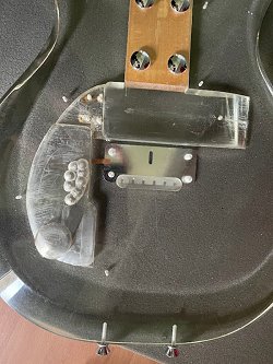
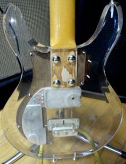
At left and right, a backside look at the pickup channel and control cavity. As Tom points out "The routing of the acrylic for the control cavity
looks very much like it's for the bass guitar model." Truer words were never spoken, for as seen here, the curved routing of the acrylic leading
towards the control cavity is virtually identical to the routing of the bass guitar model that we all know today (routed pickup channel not
withstanding).
|
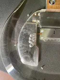
But more importantly, notice at left, a latter day Dan Armstrong bass guitar, verified as such being it features a pickup set-screw.
Notice the curvature of the routing in the body that leaves the pickup cavity and continues back towards a control cavity routed and shaped exactly
like that seen on Tom's guitar; thus giving credence to his theory that the body was likely started as a bass model, but went through many
changes along the way - not the least being that pickup channel on his guitar.
|
|
|
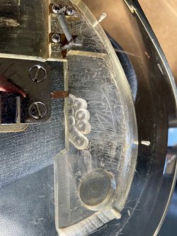
Tom continued, stating "Upon looking at the routing for the control cavity, and in particular where the pickups would connect, I noticed that there was a raised section
with screw terminals for the pickup connections. Comparing images on this site and the Dan Armstrong Registry, I realised that the control routing matched that of the early basses,
rather than the guitar models. In addition, I could see that the control cavity was originally routed for the volume & tone controls as well as the output jack. There is clearly
a second route in the control cavity where the switch routing was added - plus a series of minor drilled holes located approximately where the volume & tone pots would reside over
- but I dont believe that these shallow holes were factory)."
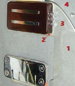
At left is the acrylic body of Tom's guitar while at right - the body of my Dan Armstrong bass. In both photos the red numbers represent the depth
of the routing - with 1 being the deepest,and 4 being the most shallow. In both cases the control cavity #1 is the deepest, while the pickup cavity
#2 is more shallow. Even more shallow is #3 which is where the bass pickup makes the electrical connections to the electronics in the control cavity
via screws that turn and tighten into drilled and tapped holes in the acrylic. Finally, #4 is the top of the clear body.
What is interesting however, is the placement of the tailpiece. At right, the tailpiece on my Dan Armstrong bass is obviously placed further back
in order to achieve proper intonation of the instrument. But as seen on the left, and on a body that had the control cavity routed like that on a
bass instrument, the bridge/tailpiece combo has been placed further forward, exactly like on the guitar model.
But as mentioned earlier, there are no other holes that were at one time drilled & tapped in the body for a tailpiece further back which further
supports Tom's statement that "the body was originally started as a bass", and for whatever reason(s) it was put aside, and experimented on
as a guitar model.
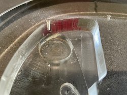
Seen at left and right Tom states "As seen from the top of the guitar you can see some light markings in the control cavity where the switch
routing was roughed out. Ironically, these very same markings from the router bit in the switch area are identical to the markings seen in the string
ball-end routing cavity - as the bit left the exact same pattern.
What this all means is that despite the curved, and layered shape of the control cavity and lack of banana plugs - this body is not a bass that was
later converted to a guitar model as the tailpiece is located closer to the neck, just where it should be for the guitar model. Also, there are no
additional holes in the acrylic body where a bass tailpiece would have once been anchored and the bass models did not even have a selector switch
until 1971."

|
At left, Tom drove his guitar over to Angela Arnott (the guitar angel), who is a professional luthier and has been repairing instruments for over 30 years. Angela is one of the UK's
leading vintage guitar restoration specialists and Tom goes on to say "I found Angela when the guitar was on route to me from America. Initially I was just wanting the hole in the
headstock to be repaired. I saw that a local vintage guitar dealer ATB Guitars hired Angela, and thought
she must therefore be highly skilled and used to working with vintage guitars. Her evaluation led to more work, including replacing the truss rod and refretting the neck, on top of the
bootstrap repair to the back of the headstock.""
Tom finished, stating "Before I had the chance to take it to her I had ordered some male banana jacks, and pickups from Aaron Armstrong in the UK (reissue plug in types, thinking
they would fit the guitar). I left her the guitar, the original pickup, a reissue pickup and the banana jacks. I was planning to source the control pots and selector switch and wire
them into the guitar myself."
|
|
|
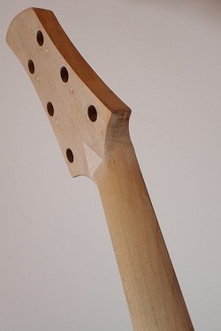
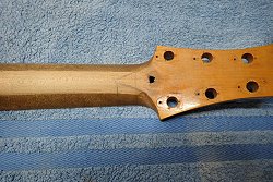
At left, Angela no doubt took a long hard look at the hole through the neck. At right, and after her initial inspection of the guitar neck she discovered that the truss rod was
not doing anything at all. When I asked her, Angela stated "The fretboard was removed to investigate the non functioning truss rod and was not based on the repair of the hole."
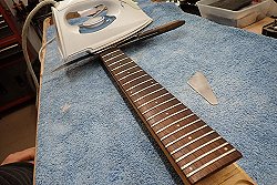
On the right, and using heat from an iron, along with a little help from a knife, the rosewood fingerboard gets removed from the maple neck in order to install a new truss rod.
Above left, the maple neck with the fingerboard removed. Surprisingly, only small pieces of fillet were found at the beginning and end of the neck with nothing in-between. At right,
Angela's son Tig who is an engineer turned luthier has been working full time with her for seven years. According to Angela "His engineering skills have brought many innovative ideas
to solving unusual problems which crop up with vintage and oddball guitars from time to time." Here, Tig is using a hand saw to remove both of the small fillets so that the old truss
rod can be removed and replaced.

|
With the fillets removed the truss rod can be seen lying in its routed channel. Angela described their findings to Tom once the fingerboard and truss rod were removed from the neck,
stating We've made a start on the neck and have removed the fretboard. I'm somewhat puzzled by the truss rod design and installation. It's deep in a flat channel (rather than a
concave channel) with no fillet over it, other than those two small pieces that Tig removed."
|
Angela continues, stating "From an engineering perspective the truss rod couldn't possibly work as it couldn't adjust in order to compensate for string pull. Any tension on the
rod would continue to pull the neck in the very same direction as the pull from the strings. Only if you could clamp it over-straight would there be the possibility of getting the
neck to pull in the opposite direction. Even then, this would only work until string tension was applied once again."
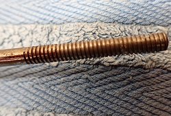
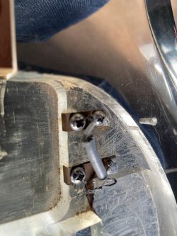
At left, with the truss rod removed, the anchor of the truss rod can be seen. According to Angela, "The rod itself was welded to the anchor." At right, something quite
surprising as Angela states "The mind boggles, I've never encountered such a rod set up. Oddly, the threaded portion of the rod is 'mashed' for its entire length. It seems to have
been cut with one die, then chased down with another, causing the threads to flatten."
Above left and right, with the fingerboard removed, Angela & Tig studies both the unusual truss rod channel as well as the hole in the backside of the neck. She also removes and cleans up
any left over glue residue. Notice too, that the faux-wood veneer has been removed from the headstock.
Above left and right, Angela thoroughly cleans up the top and bottom side of the fingerboard.
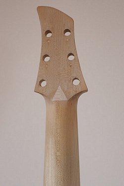
Angela states "A backstrap repair was originally planned for this hole, but with the reworked truss rod channel and different truss rod, there was the opportunity for a much simpler
inlaid triangle repair to fill the hole because the end of the rod now sits further forward, no longer in contact with the hole area. I believe that the hole was caused by the adjusting
wrench breaking through as there was no clearance at all behind the adjusting nut with the original truss rod layout."
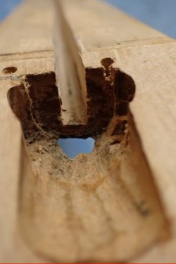
As for the hole in the backside of the neck, Angela made a 'plug' of sorts. Angela states "Sadly I have no photos of the triangle piece being made. It was cut from 4mm thick
quartersawn maple, then the neck hole area was cut slightly smaller - so that the triangle could have a rebate around its edge enabling it to be inlaid into the neck. This means it's
supported on all sides. The area was then shaped to follow the neck contouring."
At left and right, a Gibson truss rod lies nearby and will be installed after Angela fills in the truss rod channel to give a concave bow to it. In the enlarged views, notice how an
arrow is drawn in pencil to show where the nut resides.
|
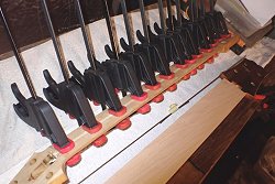
As seen at left, with the new truss rod in it's channel the fillet is glued in place. Lastly, a series of clamps are applied to hold and secure everything until the glue has dried.
|
Above left, with the new fillet secured, the new truss rod with acorn nut can be seen. Notice a metal plate has been placed behind the acorn nut to give the nut something to bear
against. Here too, the inner side of the inlaid triangle repair can be seen.
Above right, and seen better in the enlarged view the anchor for the other side of the new truss rod can be seen. It's located a bit more forward than the original anchor. Better seen
in the enlarged view, the anchor point for the original truss rod was located further back. It was actually in the tongue of the neck and can be seen as well. It has since been filled
in being this new truss rod has replaced it.
Above left, and seen better in the enlarged view, notice the 1st and the 23rd frets are removed prior to gluing the rosewood fingetboard to the maple neck. With the two frets removed
and the fingerboard lined up, small holes are drilled in and through the fret tang slots of the aforementioned frets, one up on the first fret 6th string, the other on the 23rd fret 1st
string area.
With the glue applied to the bottom of the rosewood fingerboard the two nails are inserted through the fingerboard fret slots and into the holes in the neck, thus assurring that the
fingerboard won't slip or slide around once glued and clamped in place. At right, and better seen in the enlarged view, with the clamps in place and tightend down, you can see one of
the alignment nails up at the 1st fret of the 6th string helping to secure the fingerboard in place while the glue dries.
next
menu
Names and images are TMand © Dan Armstrong / Ampeg. All rights reserved.
All other names and images are TMand © of their respective owners. All rights reserved.
|
| |