Finding schematics for your Dan Armstrong product can either be relatively simple, or extremely difficult as some
drawings are fairly common while others are exceedingly rare. Even then, trying to find the right parts or components
so many years later can be problematic at best. Nobody understood that more than Chuck Wojack who was head of Grafton Electronics
- maker of the reissue Dan Armstrong effects units in the early 2000's. When I interviewed him at the time about recreating Dan's effects units
he stated "The most difficult challenge was finding components that would closely match the specifications of the original
components made back then."
When I asked him about schematics of all the Dan Armstrong effects units that are available on the Internet, he went
on to add "The problem with all the schematics on the Internet and everywhere is that some are just plain incorrect, and
the ones that are correct reveal components that either are not available any longer - or if they are the specs of the
component have changed and are now different than what they were back then, and if the specs of the actual component
have not changed - the manufacturing process in the way the component is now made..... has."
The bottom line is - although the following schematics show the components in the various Dan Armstrong products
it is wise to keep in mind that components have changed over the years and may not perform as good, or exactly like
the original. As such, the end result may be different than what is expected, or how things may have sounded in the
late 1960's through the 1970's. It's just something to keep in mind while repairs are underway.
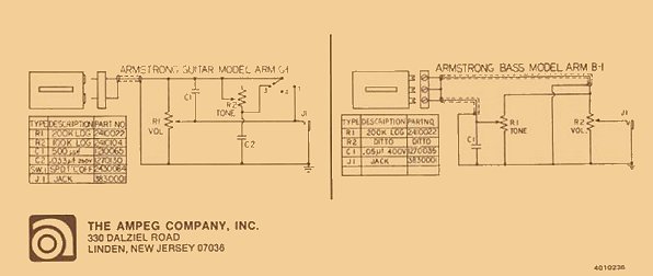 photo courtesy of Bill Richardson
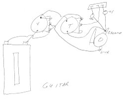
Above, a 1969 schematic of the wiring diagrams for the Dan Armstrong · Ampeg guitars and basses revealing the
earliest wiring designs. The drawings are actually on the back page of the owners manual that accompany the instruments.
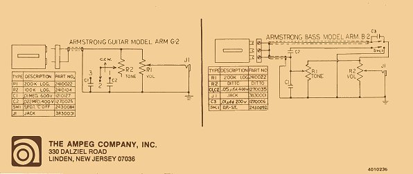 photo courtesy of Bill Richardson
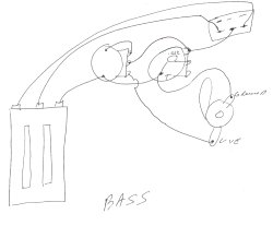
Seen above, a 1970-71 schematic of the wiring diagrams for the Dan Armstrong · Ampeg guitars and basses which reveal
changes made to the wiring designs as a result of Ampeg's Product Bulletin #17 Procedures For Updating Armstrong Guitars and Basses.
Above left and right, the reissue Dan Armstrong · Ampeg instruments never had printed schematics like back then.
When I asked Kent Armstrong if he knew how they were wired he graciously took the scratchplates off his reissue Dan Armstrong
instruments and made these hand drawings of the wiring which are shown here, courtesy of Kent Armstrong.
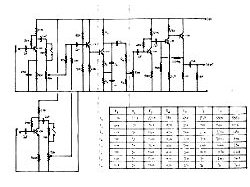
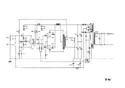
Above left, the schematics of the pre-amp section can be seen while the enlarged view shows the individual components.
According to Dan, the pre-amp section of the Dan Armstrong amplifiers are identical, and only the power amp stages
being the only thing that differentiates the models. More about it can be read in the amps section.
At upper right, and seen better in enlarged view, the schematics of the Dan1 amplifier - which is a 30 watt RMS guitar
amplifier which can be seen in the amps section.
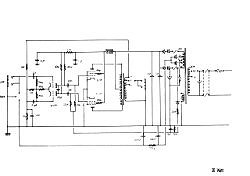
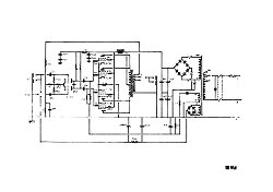
At upper left, schematics for the Dan2&3 amplifiers which are 60 watt amplifiers with the Dan2 being a combo type amp
that has two 12" speakers. The Dan3 is the same type of head, but only the piggyback head itself. Both of these amps can
be seen in the amps section, while at the enlarged view here will depict the internal components.
At upper right are the schematics for the Dan4 piggyback head which is a 100 watt amp head, with the internal components
better seen in the enlarged view. Unfortunately, at this time I do not have any drawings for the 200 watt RMS Dan5 amp
head. All the above drawings are available as a PDF file and can be seen by left clicking or downloaded by right clicking
here.
|
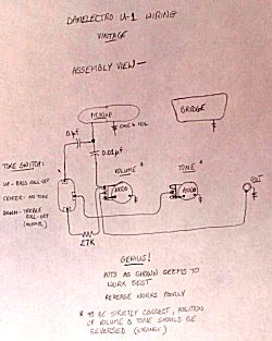
At left is a hand drawn schematic of the wiring for the DanElectro U-1 bass guitar. Seen in the DanElectro section of this site Dan Armstrong had modified many of the guitars and basses
that were left over after the DanElectro plant had closed.
Along with the pickups Dan sometimes made minor changes to the control cavities of these instruments. If you are having any
issues with a DanElectro U-1 or a Dan Armstrong Modified equivalent, these drawings could be helpful. Photo courtesy of Tony Senatore.
|
menu
Names and images are TMand © Dan Armstrong / Ampeg. All rights reserved.
All other names and images are TMand © of their respective owners. All rights reserved.
|
| |